1. Why Standard Power Transformers Fail in Renewable Grids: An Engineering Deep-Dive
The accelerated global transition toward utility-scale solar photovoltaic (PV) plants, onshore/offshore wind farms, and battery energy storage systems (BESS) has fundamentally altered grid dynamics. Traditionally, electrical step-up power transformers were engineered for centralized fossil-fuel power plants or standard utility distribution networks operating under stable 50/60 Hz sinusoidal voltage waveforms with predictable linear loads. Applying conventional grid transformers directly to renewable energy generation systems, however, consistently results in unexpected thermal runaway, insulation premature aging, localized hotspot formation, and catastrophic dielectric breakdown.
⚡ Information Gain: The Physics of Inverter-Induced Transformer Stress
Key Insight for B2B EPC Engineers: Solar PV and wind power generation relies on Pulse-Width Modulation (PWM) solid-state inverters. Unlike utility generators, inverter outputs inject high-frequency Total Harmonic Distortion (THD) into the low-voltage (LV) transformer windings. Harmonics produce stray flux eddy losses that scale with the square of the harmonic frequency ($I_h^2 \cdot h^2$). A standard distribution transformer operating under a 13th harmonic current profile will experience winding eddy current losses up to 169% higher than its rated design parameter, causing severe thermal degradation of cellulose insulation paper.
Furthermore, renewable energy power transformers operate under unique environmental and electrical stress vectors that demand purpose-engineered electro-magnetic designs compliant with IEC 60076-16 (the global benchmark for wind turbine and solar application transformers). These challenges include:
- Dynamic Thermal & Solar Irradiance Cycling: Solar PV transformers experience daily zero-to-peak load ramps, going from 0% capacity at night to 110% peak thermal rating at solar noon under desert ambient temperatures reaching 50°C. Wind power transformers endure sudden wind-gust load spikes and sub-synchronous resonance (SSR).
- PWM Switching Voltage Stress ($dV/dt$ Spikes): Modern IGBT/SiC-based central inverters generate steep voltage rise times ($dV/dt$ exceeding 3 kV/µs). High $dV/dt$ transients cause non-uniform voltage distribution across the initial turns of the transformer LV winding, leading to inter-turn insulation puncture if not shielded properly.
- DC Component Injection & Magnetic Core Saturation: Inverter control loops can inject small DC bias currents into the transformer LV windings. Even a minimal DC offset (less than 0.5% of rated current) shifts the transformer core operating point along the hysteresis loop, driving the magnetic core into asymmetric saturation, escalating magnetizing current, sound level, and excitation losses.
- Multi-Inverter Parallel Resonance: Large solar blocks utilize multiple central inverters connected to multi-winding transformers (e.g., dual LV or quad LV windings). Without specialized electrostatic shields between windings, cross-coupling harmonic currents flow between parallel inverter bridges, inducing control loop instability and trip-outs.
2. Strategic Product Catalog: Volta Renewable Energy Power Transformers
To solve these complex power quality challenges, Volta Transformers (manufactured by Volta Green Energy Pvt. Ltd. under the Pooja Group of Industries) engineers specialized, heavy-duty Renewable Energy Power Transformers tailored to specific clean energy project architectures. Below are our primary product recommendations for global utility buyers and EPC procurement specialists.
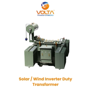
Specifically custom-engineered for 1500V DC central inverter blocks. Featuring isolated dual or quad low-voltage (LV) windings with independent electrostatic shields to couple up to four central inverters into a single medium-voltage step-up transformer (up to 33 kV / 66 kV).
- Capacity Range: 1 MVA up to 12.5 MVA
- Harmonic Rating: K-Factor K-9 to K-20 custom design
- Shielding: Copper electrostatic shield grounded between HV & LV
- Fluid Type: High flash-point Mineral Oil or Synthetic Ester
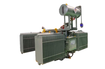
Engineered for installation inside wind turbine towers or nacelles. Designed to withstand severe mechanical vibrations, extreme ambient temperature variations, and high cyclic torsional fatigue caused by wind gust velocity changes.
- Design Options: Compact Liquid-Filled or Dry-Type Cast Resin
- Vibration Withstand: Reinforced core frame & tank structure
- Thermal Class: Class H insulation for dry-type / Ester liquid
- Voltage Class: Up to 36 kV / 66 kV grid connection
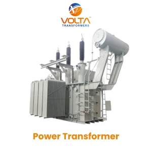
Bi-directional power flow transformers designed for utility-scale BESS facilities. Engineered to seamlessly transition between charging (step-down power mode) and discharging (step-up power mode) several times daily without dielectric fatigue or magnetic hysteresis drift.
- Duty Profile: Dynamic 4-Quadrant Bi-Directional Loading
- Thermal Endurance: Reduced winding temperature rise (55°C/50°C)
- Short Circuit Resilience: Dynamic short-circuit force tested
- Monitoring: Integrated fiber-optic hotspot sensing
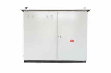
Factory-assembled, plug-and-play outdoor substations integrating high-efficiency inverter transformers, Ring Main Units (RMU) SF6/Vacuum switchgear, and Low Voltage distribution panels inside a weather-proof enclosure.
- Enclosure Protection: IP-54 / IP-55 Corrosive Resistant Metal
- Footprint: Ultra-compact design minimizing site civil work
- Safety: Internal arc tested according to IEC 62271-202
- Efficiency: High efficiency compliant with IS 1180 Part 1 Level 3
Technical Comparison: Standard Grid vs. Volta Renewable Energy Power Transformers
The table below highlights the crucial electro-technical differences that distinguish standard distribution/power transformers from Volta’s custom-built Renewable Energy Power Transformers.
| Technical Design Vector | Standard Distribution & Grid Transformer | Volta Renewable Energy Power Transformer | Engineering Benefit to Project LCOE |
|---|---|---|---|
| Applicable Standard | IS 2026 / IEC 60076-1 | IEC 60076-16 / IEEE C57.159 | Full grid code compliance and guaranteed reliability under inverter loads. |
| Harmonic Capability | Designed for K-1 (Sinusoidal 50/60 Hz only) | K-4, K-9, K-13 up to K-20 rated | Prevents transformer overheating caused by 5th, 7th, 11th & 13th inverter harmonics. |
| Winding Configuration | Single LV & HV Winding per phase | Dual LV, Triple LV, or Quad LV Windings | Allows direct connection of 2 to 4 central inverters without cross-circulating currents. |
| Electrostatic Shielding | Not present (Standard insulation only) | Grounded Copper Shield between HV & LV | Attenuates high $dV/dt$ switching surges and prevents noise coupling to grid. |
| Flux Density Design | 1.65 to 1.72 Tesla (Standard saturation point) | Reduced 1.45 to 1.55 Tesla maximum | Prevents core saturation caused by inverter DC bias injection and voltage variations. |
| Conductor Technology | Standard CTC or Paper Covered Copper | Continuously Transposed Conductors (CTC) with stray flux control | Minimizes eddy current losses and localized hot-spot temperatures in windings. |
| Dielectric Fluid Option | Standard Mineral Oil (Flash point ~140°C) | Natural / Synthetic Ester Fluid (Flash point >300°C) | 100% biodegradable eco-safety and Class-K fire hazard mitigation. |
3. Future Procurement Trends in Renewable Transformers (2026–2035)
As global utility buyers, IPPs (Independent Power Producers), and EPC corporations evaluate long-term supply chain strategies, transformer procurement is shifting from initial capital expenditure (CAPEX) evaluation to Total Cost of Ownership (TCO) and Levelized Cost of Energy (LCOE) optimization. Key procurement trends shaping the industry include:
Environmental regulations and ESG mandates are accelerating the replacement of mineral oils with natural ester (vegetable-based) and synthetic ester fluids. Ester liquids have a fire point exceeding 300°C, rendering them fire-safe without expensive deluge fire walls. Furthermore, ester liquids are 100% biodegradable within 28 days, protecting sensitive soil and groundwater in remote solar and wind farms.
Future procurement specifications mandate smart transformers equipped with real-time Dissolved Gas Analysis (DGA), moisture-in-oil sensors, and fiber-optic winding hotspot probes. Integrated IoT gateways transmit health telemetry directly to central SCADA systems, enabling predictive maintenance algorithms to prevent catastrophic outages.
With grid operators enforcing strict EU Tier 2 and Indian BEE efficiency norms, transformer cores are incorporating ultra-low-loss Amorphous Metal alloys and Domain-Refined Cold Rolled Grain Oriented (CRGO) silicon steel. This dramatically lowers no-load losses during night-time zero-generation hours in solar parks.
As power grids shift from synchronous generators to inverter-dominated supply, grid-forming (GFM) inverters are being deployed to provide synthetic inertia. GFM inverters subject step-up transformers to rapid transient phase-angle shifts. Next-generation transformer procurement demands enhanced mechanical short-circuit withstand validation under extreme dynamic stress.
4. Key Industry Development Trends: Meeting Evolving Grid Codes
The rapid expansion of clean energy has led transmission system operators (TSOs) and distribution system operators (DSOs) worldwide to tighten grid interconnection requirements. Renewable Energy Power Transformers are at the frontline of grid code compliance, driving major engineering advancements:
A. High-Frequency Harmonic Mitigation & K-Factor Engineering
Inverter switching causes continuous harmonic currents that circulate within transformer windings. Advanced electro-magnetic modeling tools allow engineers to calculate harmonic loss factors ($F_{HL}$) and design custom K-Factor rated transformers (K-4 up to K-20). By selecting optimal conductor cross-sections, multi-strand transposed strip copper, and cooling duct distributions, internal hot-spots are kept strictly within IEEE C57.110 limits.
B. dV/dt Surge Attenuation & Winding Insulation Topology
The high switching speed of modern Silicon Carbide (SiC) and IGBT inverters creates steep voltage wavefronts ($dV/dt$) that can generate voltage peaks twice the nominal value across the first turns of the LV winding. Modern manufacturing incorporates electrostatic shielding, interleaved winding geometry, and high-dielectric-strength Nomex/Epoxy insulating materials to withstand continuous voltage stress without partial discharge degradation.
C. Minimizing Low-Load & No-Load Operating Losses
Solar PV plants operate at zero power output for approximately 12 to 14 hours every night, yet step-up transformers remain energized from the medium-voltage grid, continuously consuming core excitation energy (no-load loss). Advanced core-frame clamping, step-lap 45-degree mitered core jointing, and laser-scribed CRGO steel selection minimize core magnetizing current, reducing annual auxiliary energy losses by up to 25%.
5. Enterprise Advantage: Why Global Procurement Leaders Trust Volta Transformers
Selecting the right manufacturing partner for critical power infrastructure requires verifying rigorous quality systems, physical infrastructure capabilities, and operational experience. Volta Transformers, a flagship brand owned by Volta Green Energy Pvt. Ltd. and part of the distinguished Pooja Group of Industries (Established in 2001), stands as a premier transformer manufacturer in India.
Experience
State-of-the-Art Vadodara Manufacturing Facility
Headquartered in Vadodara, Gujarat — India's premier electrical industrial hub — Volta Transformers operates a high-capacity manufacturing facility capable of building transformers up to 25 MVA / 66 KV class. Our operations adhere strictly to international quality frameworks.
ISO 9001:2015 Quality Management System
Full traceability across raw material procurement, copper conductor purity testing, core assembly, and final vacuum drying.
BIS Approved — IS 1180: Part 1: 2014
Certified compliance by Bureau of Indian Standards for energy-efficient liquid-immersed distribution transformers.
500+ Satisfied Clients Globally
Trusted across domestic and international markets, supplying power utilities, industrial complexes, and major renewable EPCs.
Rigorous Quality Assurance & In-House Testing Laboratory
Every Volta transformer undergoes exhaustive routine and specialized type testing inside our advanced testing laboratory before dispatch. Our quality assurance protocol includes:

Precision Engineering
Computerized 3D electro-magnetic finite element analysis (FEA) to calculate impulse voltage stress and stray magnetic flux distribution.

Routine Dielectric Testing
Separate source AC voltage withstand testing, induced overvoltage testing, winding resistance, turns ratio, and vector group verification.

Vacuum Drying & Fluid Processing
High-vacuum pressure drying ovens ensure core-coil assembly moisture levels remain below 0.8%, followed by automated vacuum oil filling.

Full Lifecycle Technical Support
Dedicated commissioning supervision, field installation guidance, and global spare parts support for complete peace of mind.
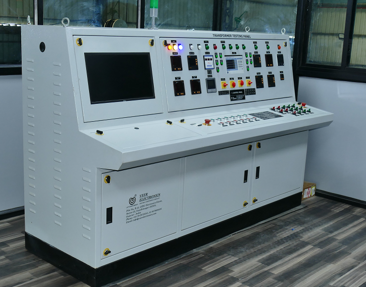
The Volta Transformers engineering and production team at our Vadodara manufacturing facility in Gujarat, India.
6. Frequently Asked Questions (FAQ) for Renewable Power Transformers
Below are technical answers to the most frequent questions posed by global procurement managers, electrical consultants, and EPC engineers when evaluating transformers for renewable energy installations.