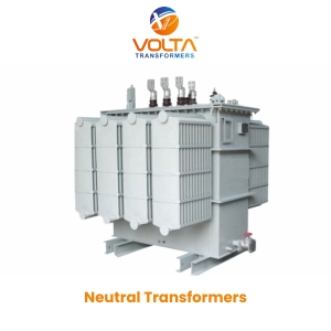
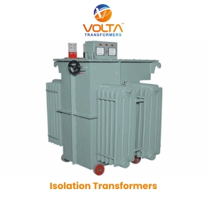
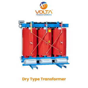
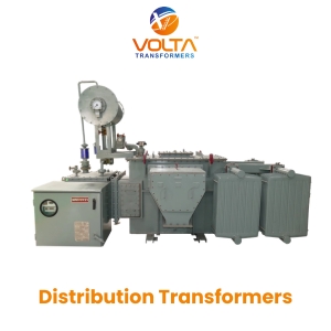
1. Understanding Neutral Transformers: Fundamentals, Vector Topologies & Zero-Sequence Dynamics
In modern electrical power distribution networks, medium-voltage transmission grids, industrial processing plants, and renewable energy collection substations, three-phase three-wire Delta ($\Delta$) connected systems are frequently deployed due to their economical conductor utilization and line-voltage stability. However, ungrounded Delta networks present a critical electrical vulnerability: they lack a physically accessible neutral point ($N$).
When an ungrounded Delta system encounters a single line-to-ground (SLG) fault, ground fault current cannot easily return to the power source. Instead, the phase voltages of the two unfaulted lines rise relative to ground by a factor of $\sqrt{3}$ (or up to 173% of nominal phase-to-ground voltage). Left unmitigated, this voltage escalation creates destructive transient arcing overvoltages (reaching over 300% to 500% of normal system peak), causing catastrophic insulation breakdown in step-up transformers, switchgear, underground cables, and connected rotating machinery.
A Neutral Transformer (commonly termed a Neutral Grounding Transformer, Grounding Transformer, Earthing Transformer, or Zigzag Transformer) is an electromagnetic apparatus engineered specifically to create a stable, physical neutral reference point in ungrounded Delta networks or ungrounded Wye systems. By connecting a Neutral Transformer to the 3-phase busbars, electrical engineers can establish a controlled grounding path through a Neutral Grounding Resistor (NGR) or Neutral Grounding Reactor (NGL), successfully limiting ground-fault current magnitudes, protecting protective relays, and suppressing ferroresonance.
Information Gain Insight: How Zero-Sequence Impedance ($Z_0$) Controls Fault Protection
Unlike standard power transformers that carry continuous balanced load currents under symmetrical conditions, a Neutral Transformer exhibits extremely high magnetizing impedance under normal positive-sequence and negative-sequence operations (resulting in minimal continuous no-load losses). However, during a single-line-to-ground fault, zero-sequence currents ($I_0$) flow equally in phase through all three windings. The opposing magnetic flux generated in inter-connected core legs collapses the zero-sequence impedance ($Z_0$) to a minimal, controlled value. This unique electromagnetic behavior enables precise fault current limiting and immediate trip signaling via sensitive ground-fault protection relays (ANSI 51N / 50N).
1.1 Primary Vector Configurations: Zigzag (Zn) vs. Star-Delta (Ynd) Topology
Global procurement engineers must select between two main vector topologies when specifying neutral grounding systems. Both configurations serve the fundamental purpose of neutral derivation, yet they exhibit distinct mechanical, thermal, and economic characteristics:
- Zigzag Winding Topology (Zn / ZNyn): The Zigzag configuration utilizes a single three-phase winding structure where each core leg carries two identical winding sections wound in opposite directions connected to different phase pairs. Under balanced line-to-line voltages, the opposing magnetic fluxes cancel each other out, presenting high magnetizing impedance. When a ground fault occurs, the zero-sequence currents flow in phase across both halves of the winding, creating additive flux cancellation that offers low zero-sequence impedance. Zigzag transformers are compact, highly cost-effective, and represent the global industry standard for pure earthing applications.
- Star-Delta Winding Topology (Ynd1 or Ynd11): The Star-Delta configuration features two separate windings: a primary Star (Wye) winding with an accessible neutral point connected to ground (often through an NGR) and a secondary closed Delta ($\Delta$) winding. Under normal conditions, the secondary Delta is unloaded. Under ground fault conditions, zero-sequence current in the primary Wye induces a circulating current within the closed Delta, neutralizing zero-sequence flux in the core. While slightly larger in physical footprint, Ynd transformers allow the secondary Delta to be utilized for auxiliary power supply or local station services.
| Technical Parameter | Zigzag Winding (Zn) | Star-Delta Winding (Ynd) | Open-Delta Grounding |
|---|---|---|---|
| Primary Function | Artificial Neutral Derivation & NGR Coupling | Grounding & Station Auxiliary Power Supply | Voltage Monitoring & Residual Voltage Detection |
| Relative Physical Footprint | Compact (100% baseline) | Moderate (~125% - 140% of baseline) | Small (Instrument Voltage Transformer Scale) |
| Zero-Sequence Impedance ($Z_0$) | Very Low, customizable via winding geometry | Low, governed by primary-secondary leakage | High, limited to sensing loops |
| Auxiliary Power Capability | Optional via embedded low-voltage secondary | Inherent via secondary Delta or auxiliary Wye | Not applicable |
| Short-Time Thermal Rating | Standard 10s, 30s, or 60s rating | Continuous auxiliary + short-time fault rating | Continuous potential transformer rating |
| IEEE / IEC Standard Baseline | IEEE C57.32 / IEC 60076-6 / IS 3151 | IEEE C57.12.00 / IEC 60076-1 | IEC 61869-3 / IEEE C57.13 |
2. Precision-Engineered Neutral Transformer Product Lineup
Volta Transformers designs and manufactures a complete spectrum of neutral grounding solutions tailor-made for utility power grids, renewable energy plants, heavy industrial processing facilities, and commercial substations. Built at our state-of-the-art Vadodara manufacturing plant under strict ISO 9001:2015 quality control, each transformer undergoes rigorous zero-sequence impedance measurement, dielectric testing, and short-time thermal withstand verification.