Executive Summary & Technical Intent
In modern electrical grid management and industrial power distribution, Oil-Filled Power Transformers serve as the backbone of transmission networks, industrial plants, and renewable energy integration projects. As global power grids undergo rapid modernization toward higher efficiency, localized generation, and extreme weather resilience, procurement professionals and chief electrical engineers require precise technical knowledge to evaluate transformer architecture, thermal dissipation mechanisms, total cost of ownership (TCO), and supplier quality assurance standards.
This technical blueprint synthesizes insights across high-voltage engineering, semantic search intent mining, international electrical standards (IEC 60076, IS 1180, IEEE C57), and practical field data from over 15 years of precision manufacturing at Volta Transformers.
1. Fundamentals of Oil-Filled Power Transformers: Dielectric Dynamics & Heat Dissipation
At its core, an Oil-Filled Power Transformer relies on high-grade mineral oil or synthetic ester fluid to serve a dual function: electrical insulation (dielectric strength) and thermal energy transportation (cooling). Unlike dry-type transformers, which rely on air movement and resin insulation, liquid-immersed transformers provide exponentially superior heat transfer characteristics, allowing for higher energy density, compact footprint, and longer operational lifespan under harsh duty cycles.
1.1 Dielectric Fluid Physics and Insulation Integrity
The insulation matrix inside an oil-filled transformer consists of a solid-liquid composite system: cellulose pressboard/kraft paper impregnated with refined electrical insulating oil. The dielectric strength of the liquid—typically required to exceed 30 kV (fresh) up to 60+ kV (vacuum-processed)—prevents breakdown under high electromagnetic stress, transient overvoltages, and lightning impulses.
Proper degassing, moisture removal, and filtration during the oil-filling stage are paramount. Even micro-quantities of dissolved water (>15 ppm) or entrained air drastically reduce the dielectric breakdown voltage and accelerate thermal aging of the paper insulation, accelerating the degradation of degree of polymerization (DP) values.
1.2 Thermodynamics & Cooling Classifications
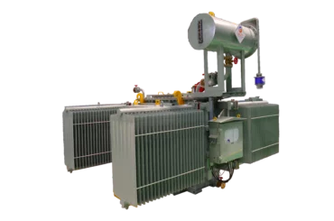
Heat generated within the core and copper/aluminum windings due to no-load losses (hysteresis and eddy currents) and load losses (I²R resistance and stray losses) must be continuously evacuated to maintain top-oil and winding hotspot temperatures below standard limits (65°C oil rise, 100°C winding rise per IS/IEC standards). Thermal circulation operates across several standardized cooling modes:
- ONAN (Oil Natural Air Natural): Thermo-siphon effect circulates oil naturally through radiators while ambient air cools the outer radiator fins naturally. Ideal for base-load distribution and sub-transmission applications.
- ONAF (Oil Natural Air Forced): Axial flow fans force air across radiator banks, boosting cooling efficiency by 25% to 40% and providing temporary peak-overload headroom.
- OFAF / ODAF (Oil Forced Air Forced / Directed): Internal oil pumps direct high-velocity oil flow straight through guided winding channels, essential for ultra-high MVA power transformers in heavy steel plants or utility substations.
2. Future Global Procurement Trends in Oil-Filled Power Transformers (2026–2035)
Analyzing global search intent and tender specifications reveals a seismic shift in how multinational corporations, EPC contractors, and state power boards evaluate transformer acquisitions. Key trends shaping future procurement include:
2.1 Transition to Biodegradable Ester Dielectric Fluids
While traditional mineral oils (IEC 60296) remain widely specified due to low initial cost, procurement tenders in North America, Europe, and coastal regions increasingly demand Natural and Synthetic Ester Fluids (IEC 61099 / ASTM D6871). Ester liquids deliver a fire point exceeding 300°C (K-class qualification), virtually eliminating explosion risks in urban substations or indoor industrial vaults. Furthermore, ester fluids are >98% biodegradable within 28 days, drastically reducing environmental liability in the event of spillages.
2.2 High-Harmonic Resilience & Inverter Duty Engineering
With the exponential expansion of utility-scale solar PV installations, wind farms, and industrial Variable Frequency Drives (VFDs), transformers are subjected to high total harmonic distortion (THD). Non-linear switching currents cause elevated skin effects, stray eddy current losses in structural steel clamp plates, and localized hotspot formation. Modern procurement mandates K-Factor ratings, electrostatic shielding between primary and secondary windings, and specialized multi-winding configurations (e.g., dual or triple secondary outputs for inverter duty applications).
2.3 IoT-Enabled Smart Transformers & Real-Time DGA Monitoring
Unplanned downtime in utility networks carries severe financial penalties. The market is rapidly standardizing on "Smart Transformers" equipped with integrated Online Dissolved Gas Analysis (DGA) sensors, fiber-optic real-time winding hotspot temperature probes, electronic oil level indicators, and automated breather desiccant monitors. These sensors transmit live diagnostic telemetry over IEC 61850 protocol to SCADA systems, enabling predictive maintenance models driven by AI algorithms.
2.4 Eco-Design Directives & Ultra-Low Loss Standards
Energy efficiency regulations—such as EU Eco-Design Tier 2 and Indian Standard IS 1180 Energy Efficiency Levels (Level 1, Level 2, Level 3)—have made loss evaluation (Capitalization of Losses) a core component of bid evaluation. Buyers no longer buy solely on purchase price; they calculate Net Present Value (NPV) based on total lifetime energy dissipation over a 30-year operational horizon using high-permeability Grain-Oriented Silicon Steel (CRGO) or amorphous core alloys.
3. Recommended Product Lineup: Technical Selection for Global Buyers
Volta Transformers designs and manufactures a comprehensive portfolio of liquid-immersed transformer solutions engineered to meet diverse environmental and load demands across 50+ countries. Below are our key product recommendations:
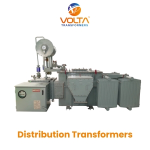
Oil-Filled Distribution Transformers
Compliant with BIS IS 1180 Part 1 (2014) and IEC 60076 standards. Ranging from 11 kV to 33 kV step-down distribution, these units feature low-loss CRGO cores, corrugation cooling panels or radiators, and robust short-circuit withstand performance.
Primary Applications: Urban distribution, industrial parks, commercial complexes, rural electrification.
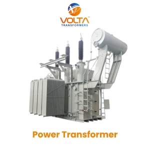
High-Voltage Power Transformers (Up to 25 MVA / 66 KV)
Designed for heavy power transmission and main step-up/step-down substations. Features On-Load Tap Changers (OLTC) or Off-Circuit Tap Changers (OCTC), rigid clamping structures to absorb short-circuit electromagnetic forces, and custom cooling options (ONAN/ONAF).
Primary Applications: Regional substations, heavy manufacturing, IPP power generation plants.
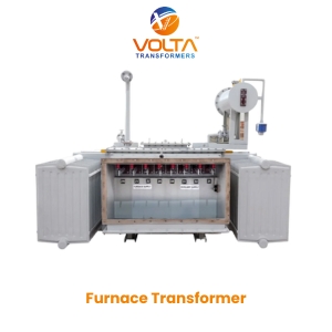
Industrial Furnace Transformers
Specially reinforced transformers built to withstand extreme electrical stresses, severe short-circuit currents, and heavy thermal cycling inherent in Electric Arc Furnaces (EAF) and Submerged Arc Furnaces (SAF).
Primary Applications: Steel plants, metallurgical smelting, ferro-alloy production, foundries.
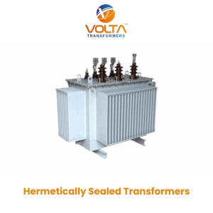
Hermetically Sealed Transformers
Completely sealed from atmospheric oxygen and moisture ingress. Flexible corrugated tank walls accommodate thermal expansion of oil without needing a conservator tank or air breather, dramatically reducing life-cycle maintenance costs.
Primary Applications: Coastal areas, high-humidity environments, chemical plants, offshore platforms.
3.5 Standardized Technical Parameter Reference Matrix
The following reference table outlines the technical specifications available across Volta Transformers' standard oil-filled power transformer series:
| Technical Parameter | Distribution Class | Substation Power Class | Inverter / Special Duty |
|---|---|---|---|
| Capacity Range (MVA) | 100 kVA to 2.5 MVA | 2.5 MVA to 25 MVA | 1.0 MVA to 12.5 MVA |
| Primary Voltage Rating | 11 kV, 22 kV, 33 kV | 33 kV, 66 kV | 11 kV, 22 kV, 33 kV |
| Vector Group | Dyn11 / Dyn5 | YNd11 / YNyn0 / Dyn11 | Dy11y11 / Dy11d0 |
| Cooling Medium | ONAN | ONAN / ONAF | ONAN / ONAF (Ester optional) |
| Insulation Level (BIL) | Up to 170 kV LI | Up to 325 kV LI | Up to 170 kV LI |
| Tap Changer Type | Off-Circuit (+/- 5%) | OLTC with RTCC (+/- 10%) | Off-Circuit / OLTC |
| Applicable Standards | IS 1180, IEC 60076, BS 171 | IEC 60076, IEEE C57.12 | IEC 60076-16, IS 2026 |
4. Enterprise Advantages: Why Global Buyers Trust Volta Transformers
Choosing a transformer manufacturer requires rigorous audit of engineering capabilities, manufacturing infrastructure, and quality control systems. Volta Transformers operates under the umbrella of Volta Green Energy Pvt. Ltd., a flagship venture of the esteemed Pooja Group of Industries (established in 2001).
4.1 State-of-the-Art Infrastructure in Vadodara, Gujarat
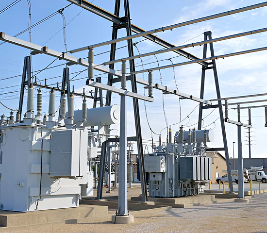
Located in Vadodara—India’s premier electrical engineering manufacturing hub—our facility spans advanced core processing bays, automated winding machines, high-vacuum oil impregnation plants, and modern fabrication units. This geographic advantage gives us access to world-class raw material suppliers (high-grade CRGO steel from top mills, 99.9% electrolytic copper conductors) and robust export logistics via major sea ports (Mundra, Kandla, Nhava Sheva).
4.2 Strict Adherence to International Quality Benchmarks
Volta Transformers maintains an uncompromised commitment to quality assurance, validated through global certifications:
- ISO 9001:2015 Quality Management System: Comprehensive traceability from raw material receiving inspection to final dispatch documentation.
- BIS Approved (IS 1180: Part 1: 2014): Certified by the Bureau of Indian Standards for energy-efficient distribution transformers up to Level 3 efficiency guidelines.
- 25 MVA / 66 KV Production Class: Proven capability to manufacture high-capacity transformers designed for stringent dynamic short-circuit endurance.
- Over 15 Years of Engineering Heritage: Supported by a seasoned team of design engineers, quality control specialists, and international project coordinators.

15+ Years Proven Track Record
Delivering specialized transformer solutions across power utilities, steel mills, solar farms, and infrastructure projects globally.

Strict Testing & Inspection
100% in-house routine testing including dielectric breakdown, impulse withstand, loss measurement, and temperature rise verification.

Precision Engineering Infrastructure
High-vacuum drying ovens, automated oil filtration plants, and computer-aided electromagnetic design modeling software.

Global Export Expertise
Serving 500+ satisfied clients worldwide with customized voltage ratings, specialized vector groups, and seaworthy export packaging.
5. Frequently Asked Procurement & Engineering Questions (FAQ)
Global electrical engineers and procurement managers frequently query search engines and AI assistants regarding technical trade-offs and operational parameters. Below are expert, data-driven answers to the most common questions:
Partner with India's Premier Transformer Manufacturer
From standard distribution units to multi-MVA power transformers and custom inverter duty designs, Volta Transformers provides engineered reliability backed by ISO 9001:2015 certification and 15+ years of operational excellence.