1. Executive Overview: The Crucial Role of Foundry Furnace Transformers in Smelting Operations
In the demanding realm of modern metallurgy, steelmaking, ferroalloy synthesis, and non-ferrous foundry operations, Foundry Furnace Transformers represent the single most critical electrical asset within the plant infrastructure. Unlike conventional power distribution units operating under predictable sinusoidal loads and steady-state grid conditions, furnace transformers are exposed to some of the most violent electrical and thermal environments engineered in heavy manufacturing.
A Foundry Furnace Transformer acts as the vital bridge between high-voltage utility transmission networks (typically 11kV, 33kV, or 66kV) and the ultra-high current, low-voltage arc or induction melting systems. Operating secondary currents often range from 10,000 Amperes to upwards of 80,000 Amperes at variable secondary voltages (often between 80V and 1,000V). The transformer must step down high grid voltages while supplying massive, dynamically fluctuating current directly into molten baths or arc electrodes.
Why Foundry Furnace Transformers Require Specialized Engineering
Standard power transformers designed according to IEC 60076 or IS 2026 are structured for balanced, continuous loads. Applying a standard transformer to a metallurgical furnace invariably leads to catastrophic mechanical winding failure, dielectric oil breakdown, or premature insulation degradation within months. Foundry Furnace Transformers demand customized core geometries, heavy-gauge interleaved copper busbar arrangements, multi-stage forced cooling systems (OFWF/OFAF), and reinforced mechanical clamping systems built to endure thousands of direct dead-short events every year.
At Volta Transformers (a premier brand of Volta Green Energy Pvt. Ltd. and part of the Pooja Group of Industries established in 2001), our engineering team in Vadodara, Gujarat, designs specialized furnace transformers tailored to withstand the exact operational profiles of Electric Arc Furnaces (EAF), Submerged Arc Furnaces (SAF), Ladle Metallurgy Furnaces (LMF), and High-Frequency Induction Smelting Systems globally.
2. Technical Product Recommendations: Custom-Engineered Furnace Transformer Solutions
Global metallurgical buyers require distinct transformer configurations based on furnace chemistry, electrode feeding mechanisms, and operational duty cycles. Below are our recommended engineering configurations for heavy foundry applications:
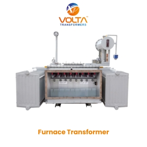
Electric Arc Furnace (EAF) Transformers
Designed for severe scrap steel melting operations characterized by frequent arc short-circuits during scrap cave-ins. Features internal OLTC regulation, heavy copper foil secondary windings, and high short-circuit withstand factors.
Get a Quote
Submerged Arc Furnace (SAF) Transformers
Engineered for continuous high-load reduction processes such as ferro-silicon, ferro-manganese, and calcium carbide production. Provides extremely wide secondary voltage variation under continuous duty conditions.
Get a Quote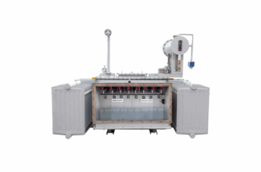
Induction & Converter Duty Furnace Transformers
Optimized for solid-state medium and high-frequency induction melting power supplies (VFD/Thyristor converters). Built with K-factor rated insulation to easily withstand 5th, 7th, 11th, and 13th harmonic currents.
Get a Quote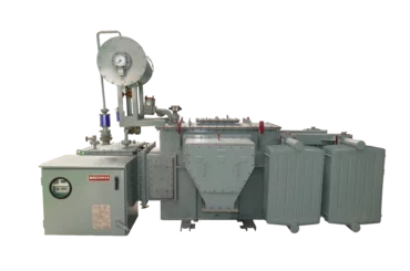
Ladle Metallurgy Furnace (LMF) Transformers
Provides precise voltage control for liquid metal refining, degassing, and alloy adjustment. Offers stable arc characteristics and fine tap-step adjustment to protect molten steel quality.
Get a QuoteComprehensive Technical Matrix: Volta Foundry Furnace Transformer Specifications
To assist procurement managers and EPC engineers in selecting the correct unit, the matrix below outlines standard technical parameters available across our production lines in Vadodara:
| Technical Parameter | Electric Arc Furnace (EAF) | Submerged Arc Furnace (SAF) | Induction Melting Duty | Ladle Metallurgy Furnace (LMF) |
|---|---|---|---|---|
| Power Rating Range | 2.5 MVA to 25 MVA | 5.0 MVA to 25 MVA | 1.0 MVA to 15 MVA | 2.0 MVA to 20 MVA |
| Primary Voltage Class | 11 kV / 22 kV / 33 kV / 66 kV | 11 kV / 33 kV / 66 kV | 6.6 kV / 11 kV / 33 kV | 11 kV / 22 kV / 33 kV |
| Secondary Voltage Range | 80 V – 600 V (Multi-tap) | 100 V – 800 V (Continuous) | 400 V – 1200 V (Converter input) | 120 V – 450 V (Fine steps) |
| Secondary Amperage | Up to 60,000 Amperes | Up to 80,000 Amperes | Up to 15,000 Amperes | Up to 40,000 Amperes |
| Voltage Regulation Method | Internal OLTC / Booster Design | On-Load Tap Changer (OLTC) | Off-Circuit / Fixed Tap | Fine-step OLTC |
| Cooling System Options | OFAF / OFWF / ONAF | OFWF / OFAF | ONAN / ONAF | ONAF / OFAF |
| Harmonic Endurance | K-Factor 13 to 20 rated | K-Factor 9 to 13 rated | K-Factor 20+ (Thyristor duty) | K-Factor 13 rated |
| Standard Compliance | IEC 60076-6 / IS 2026 | IEC 60076-6 / IEEE C57.17 | IS 1180 / IEC 60076 | IEC 60076-6 / IS 2026 |
3. Engineering Deep-Dive: Mitigating Electromechanical Stresses & Thermal Surges
For B2B buyers seeking maximum Information Gain, evaluating a furnace transformer vendor requires looking beyond basic price quotes. The true total cost of ownership (TCO) is determined by how the manufacturer solves three core electromechanical phenomena during the furnace duty cycle:
A. Dynamic Short-Circuit Mechanical Force Withstand
During arc initiation in scrap melting furnaces, the electrode frequently strikes solid metal scrap directly, creating an instantaneous dead short circuit across the secondary terminals. Under peak fault conditions, radial and axial electromagnetic forces acting on the transformer coils scale with the square of the peak current ($F \propto I_{peak}^2$).
If the winding structure is loosely clamped, these repeated dynamic forces cause cumulative displacement of the turns, destroying the inter-turn paper insulation and resulting in catastrophic turn-to-turn flashover. Volta Transformers addresses this challenge by:
- Finite Element Method (FEM) Modeling: Simulating exact electromagnetic stress distribution across all winding layers prior to manufacturing.
- High-Density Pre-compressed Pressboard: Utilizing pre-shrunk, densified insulation materials that maintain constant axial compression throughout the unit's 30-year operational life.
- Rigid Hydraulic Clamping Rings: Employing heavy steel clamping structures at the top and bottom of core-coil assemblies to ensure zero physical movement during short-circuit events.
Figure 1: Volta Transformers' high-bay core-coil assembly area in Vadodara, Gujarat, equipped with precision hydraulic axial clamping systems for furnace transformer manufacturing.
B. Managing Stray Loss & Busbar Heating at 50,000+ Amperes
When secondary currents exceed 20,000 Amperes, intense leakage magnetic fields radiate from the heavy secondary copper leads. If these magnetic fields intersect the structural steel tank or clamping frame, they induce severe eddy currents, causing localized hot spots, oil gasification, and thermal structural distortion.
Volta engineers neutralize stray eddy loss through specialized low-inductance busbar geometry. By interleaving positive and negative secondary copper bars in a multi-phase sandwich configuration, the surrounding magnetic fields cancel each other out ($B_{net} \approx 0$). Furthermore, non-magnetic stainless steel inserts or aluminum shielding plates are integrated into the tank wall where secondary heavy-current bushings penetrate, completely preventing localized thermal runaway.
C. Advanced Cooling Systems: Comparing ONAN, ONAF, OFAF, and OFWF
Because foundry furnaces cycle rapidly between full load and standby, heat dissipation must be managed dynamically to avoid accelerating cellulose paper insulation aging. Below is a comparative analysis of cooling methodologies:

ONAN / ONAF Cooling
Oil Natural Air Natural / Forced: Ideal for smaller induction furnaces (up to 5 MVA). Relies on radiator banks mounted to the tank with automatic fan control during peak thermal cycles.

OFAF Cooling System
Oil Forced Air Forced: Employs submerged oil pumps to actively drive dielectric oil through external forced-air heat exchangers. Provides rapid cooling response during continuous EAF melting heats.

OFWF Water-Cooled System
Oil Forced Water Forced: The gold standard for ultra-compact, high-capacity foundry transformers. Uses shell-and-tube water heat exchangers connected to plant cooling towers for maximum heat extraction.
4. Future Procurement Trends in Foundry Furnace Transformers (2026–2035)
As global metallurgical industries pivot toward carbon neutrality, energy optimization, and smart factory automation, the procurement parameters for Foundry Furnace Transformers are undergoing a profound transformation. Global buyers must prepare for several emerging technological shifts:
1. The Transition to Green Steel & Hydrogen DRI Furnaces
With worldwide steelmakers shifting away from coal-based blast furnaces toward Direct Reduced Iron (DRI) paired with green hydrogen and Electric Arc Furnaces, furnace transformer demand is surging. However, DRI scrap feeds contain higher gangue content, requiring longer melting cycles and higher power-on times. Future procurement specifications require transformers with 100% continuous duty cycle thermal ratings rather than traditional intermittent overload ratings.
2. Integration of AI-Powered Real-Time DGA Monitoring
Modern foundries cannot afford unplanned transformer outages, which can freeze molten metal in ladles and cause millions of dollars in equipment damage. Forward-thinking procurement officers are specifying furnace transformers pre-fitted with multi-gas Dissolved Gas Analysis (DGA) sensors connected directly to industrial AI diagnostic platforms. These systems track hydrogen ($H_2$), acetylene ($C_2H_2$), and ethylene ($C_2H_4$) buildup in real-time to predict tap-changer contact wear and micro-arcing before failure occurs.
3. Adoption of High-Flashpoint Natural & Synthetic Ester Fluids
Environmental regulations and indoor foundry fire safety standards are pushing plants away from conventional mineral transformer oil. Synthetic and natural ester dielectric fluids offer fire points above 300°C (Class K insulation rating) compared to 140°C for mineral oil. Moreover, ester fluids absorb moisture from solid paper insulation, significantly extending transformer operating life under heavy thermal stress.
4. Demand for Ultra-High Current Multi-Phase Outputs
To reduce flicker on public power grids and maximize arc stability, new mega-foundries are adopting 6-phase and 12-phase secondary rectifying furnace transformers. By splitting the secondary output into multiple phase-shifted windings, harmonic distortion fed back into the high-voltage grid is reduced by up to 85%, minimizing the need for expensive external static VAR compensators (SVC).
5. Key Development Trends in Furnace Transformer Technology
Technological advancement in furnace transformers is centered around improving electrical efficiency, reducing footprint, and enhancing electrical insulation resilience. The primary design innovations currently reshaping the industry include:
- Amorphous & High-Permeability CRGO Core Steels: Utilizing laser-scribed Domain Refined Cold-Rolled Grain-Oriented (CRGO) steel laminations to reduce no-load core losses by 20% to 30%, decreasing baseline electrical consumption during furnace idling.
- Continuously Transposed Conductors (CTC) with Epoxy Bonding: Replacing bulky rectangular copper conductors with CTC cable bonded by thermally activated epoxy resin. This dramatically reduces eddy current losses within the winding while providing superior mechanical rigidity against short-circuit forces.
- Hybrid Insulation Insulation Systems: Combining DuPont Nomex high-temperature synthetic paper on critical winding turns near tap outputs with high-purity cellulose paper elsewhere, allowing hot-spot operating temperatures up to 140°C without accelerating thermal aging.
- Integrated Vacuum On-Load Tap Changers (OLTC): Conventional OLTCs operating in oil generate arcing products that contaminate dielectric oil during tap switching. Modern furnace transformers utilize vacuum-interrupter OLTC technology, eliminating arcing in oil and extending contact service intervals from 50,000 operations to over 300,000 operations.
Why Global Procurement Teams Choose Volta Transformers
Volta Transformers (manufactured by Volta Green Energy Pvt. Ltd.) stands as an authoritative beacon of engineering precision in India’s manufacturing hub of Vadodara, Gujarat. Operating under the umbrella of the Pooja Group of Industries (established in 2001), we offer over two decades of technical mastery in high-stress transformer design.
Our state-of-the-art facility manufactures custom transformers up to 25 MVA / 66 KV class, serving over 500+ satisfied industrial clients across domestic and international markets in steel, mining, chemical, and heavy manufacturing sectors.
6. Global Procurement & Engineering FAQ: Foundry Furnace Transformers
Below are authoritative responses to the most frequent technical and commercial questions posed by international buyers, plant managers, and electrical consultants:
Partner with a World-Class Furnace Transformer Manufacturer
Contact our senior engineering team today to review your furnace electrical single-line diagrams (SLD), custom tap requirements, and duty cycle specifications. We deliver precision-built, ISO 9001:2015 certified transformer solutions directly from Vadodara, Gujarat to global industrial sites.
Get a Quote