Industrial Transformers & Electrical Substation Units
Explore our top-tier wholesale current transformers, isolation units, auto-transformers, and compact substations customized for international OEM/ODM projects.
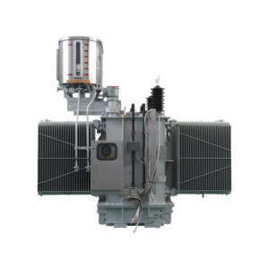
CE Certified 55kV 2x27.5kV 10MVA Ultra-Low Loss Auto Transformer
Get a Quote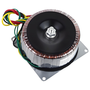
Customizable 300W Toroidal Isolation Auto Transformer
Get a Quote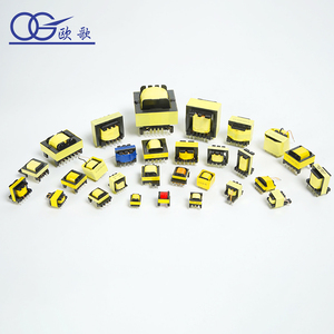
EF25 Constant Current Ferrite Core Electrical Transformer
Get a Quote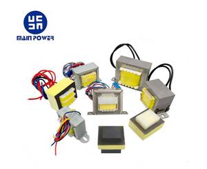
Square 60Hz 220V Industrial Auto Distribution Transformer
Get a Quote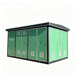
Modular Three-Phase Substation (YBW Model IP44)
Get a Quote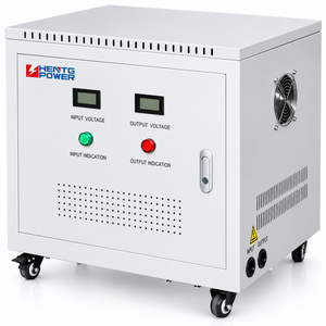
10KVA 220V to 380V 3-Phase Toroidal Step Up/Down Transformer
Get a Quote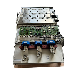
6SL3352-7AE32-1AA1 S120 MICROMASTER Replacement Fan Transformer
Get a Quote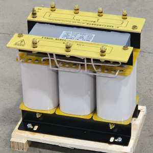
SBK 3-Phase Isolation & Auto Transformer (10KVA-150KVA)
Get a QuoteComprehensive Guide to Current Transformers (CT): Architecture, Magnetic Physics & Selection Criteria
In modern electrical power distribution, high-voltage transmission, and industrial automation networks, the Current Transformer (CT) serves as the indispensable baseline component. Functioning as an instrument transformer, a CT steps down high primary currents (ranging from hundreds to tens of thousands of amperes) into standardized, manageable secondary currents (typically 1A or 5A). This secondary output safe-guards sensitive metering instruments, digital protection relays, and SCADA monitoring units from direct contact with high-voltage lines while preserving precise proportional current signal fidelity.
Magnetic Core Physics & Flux Saturation Dynamics
The operational core of any current transformer lies in electromagnetic induction governed by Faraday's Law and Ampere's Circuital Law. Primary current flowing through the primary conductor creates an alternating magnetic flux in the magnetic core. This flux induces a secondary current in the tightly wound secondary coil. However, optimal performance depends entirely on core material properties and saturation profiles:
- Grain-Oriented Silicon Steel (CRGO): Traditional standard offering high saturation flux density ($B_{sat} \approx 1.9\text{T}$ to $2.0\text{T}$), ideal for protection class CTs (5P20, 10P20) requiring high thermal and short-circuit current withstand without structural breakdown.
- Nanocrystalline & Amorphous Alloys: Modern high-permeability materials exhibiting extremely low coercive force and ultra-low core loss. Essential for revenue-grade metering CTs requiring Class 0.2S and Class 0.1 accuracy across ultra-wide dynamic current ranges (from 1% up to 120% of rated primary current).
- Nickel-Iron Alloys (Mu-Metal): Used in specialized low-current measurement applications where minimum phase angle displacement and near-zero ratio error are paramount.
Accuracy Classes & Standard Compliance (IEC 61869-2 vs. IEEE C57.13)
Selecting the appropriate current transformer requires navigating global standards. International buyers must evaluate the subtle performance differences between metering CTs and protection CTs:
| Standard | CT Type | Accuracy Class | Ratio Error at $I_n$ | Phase Displacement | Primary Application |
|---|---|---|---|---|---|
| IEC 61869-2 | Metering | 0.2S | ±0.2% (at 20%-120% $I_n$) | ±10 minutes | Tariff Billing, Smart Metering, Power Quality Analysis |
| IEC 61869-2 | Metering | 0.5 | ±0.5% (at 100% $I_n$) | ±30 minutes | Commercial Distribution Switchboards, Energy Monitoring |
| IEC 61869-2 | Protection | 5P20 | ±1.0% (at $I_n$) / 5% Composite Error at $20 \times I_n$ | ±60 minutes | Feeder Protection Relays, Overcurrent & Earth Fault Units |
| IEEE C57.13 | Metering | 0.3B-0.9 | ±0.3% at rated current | ±15.4 minutes | North American Commercial Substation Utility Metering |
| IEEE C57.13 | Relaying | Class C800 | Low leakage reactance (calculable terminal voltage) | Defined by Knee Point | High-Impedance Busbar & Differential Relay Protection |
China Enterprise Advantage & Global Manufacturing Capabilities
Leveraging advanced manufacturing facilities, automated toroidal winding technology, and rigorous quality control protocols to supply worldwide OEM partners.
ISO 9001:2015 & Full Type-Tested Compliance
Every batch of current transformers produced in our facilities undergoes rigorous routine testing including ratio error, phase angle error, winding resistance, and power frequency withstand voltage tests compliant with IEC 61869-1/2 standards.
Precision Vacuum Resin Casting & Insulation
Utilizing APG (Automatic Pressure Gelation) epoxy resin casting techniques. Ensures bubble-free dielectric encapsulation, high short-circuit thermal capacity, superior mechanical rigidity, and moisture resistance up to IP67.
End-to-End Customization (OEM/ODM Engineering)
From specialized primary window dimensions for oversized busbars to customized secondary outputs (e.g., 0-5A, 0-1A, 0-333mV micro-voltage, or 4-20mA DC transducers), our R&D engineering team tailors solution packages for your regional market.
Future Procurement Trends & Technological Evolution in Current Transformers
As global energy infrastructures undergo rapid decarbonization, digitisation, and decentralized grid integration, current transformer procurement strategies are shifting dramatically. B2B procurement managers, EPC contractors, and electrical equipment wholesalers must align their supply chains with key upcoming technological trends through 2030.
1. LPIT & Optical CT Integration
Transitioning from heavy iron-core CTs to Low-Power Instrument Transformers (LPITs), Rogowski coils, and optical fiber CTs compliant with IEC 61869-10/11. LPITs eliminate dangerous open-circuit secondary high voltage hazards and fit seamlessly into smart digital substations utilizing IEC 61850 process buses.
2. High-Harmonic & Renewable Duty CTs
The surge of PV inverters, wind turbines, and EV fast-charging networks introduces severe high-frequency harmonics into distribution networks. Future CT procurement mandates cores engineered with non-linear saturation compensation to prevent overheating and measurement drift under distorted wave conditions.
3. Retrofit Split-Core & Plug-and-Play Units
Smart factory retrofits require non-intrusive current measurements without disrupting existing busbars. Demand for split-core CTs with self-locking hinges and low-voltage millivolt outputs (e.g., 333mV) is expanding at over 12% CAGR globally, driving fast-turnaround wholesale procurement.
Strategic Procurement Recommendations for Bulk Buyers
To mitigate international supply chain risks and achieve optimal total cost of ownership (TCO) when importing current transformers from China manufacturing hubs, enterprise buyers should enforce the following standard evaluation steps:
- Audit Core Saturation Calculations: Request complete Knee-Point Voltage ($V_k$) curves and excitation current curves for protection cores (Class PX, 5P20) to prevent relay blinding during extreme asymmetrical short-circuit fault conditions.
- Verify Temperature Rise Limits: Ensure thermal rating factors (e.g., $RF = 1.2$ or $1.5$ at $40^\circ\text{C}$ ambient) meet local climate installation criteria, preventing insulation degradation over 25+ year operational lifespans.
- Standardize Secondary Burden Matching: Avoid over-specifying secondary VA rating. Modern micro-processor digital relays present near-zero burden ($<0.5\text{VA}$); ordering high-burden CTs (e.g., 15VA) for electronic meters leads to ratio error distortion due to light core loading.
Need Custom Current Transformers for Your Industrial Project?
Contact our senior engineering team today for technical drawings, comprehensive laboratory test reports, and direct factory wholesale quotations.
Get a QuoteB2B Current Transformer Procurement FAQ
Clear answers to critical technical and commercial queries raised by global importers, electrical engineers, and wholesale buyers.