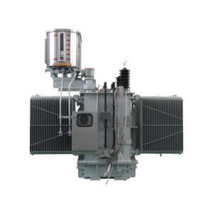
Featured Product Lineup
CE Certified Potential & Auto Transformers
Explore our industrial-grade, certified potential transformers and auto-transformer solutions customized for substations, heavy rail, industrial plants, and renewable energy grids.
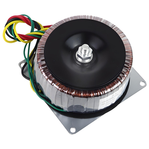
Customizable 300W Toroidal Transformer Universal Isolation Auto Transformers Multi-Voltage Output
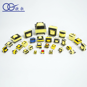
Wholesale Price EF25 Step Down Transformer Constant Current Led Driver Ferrite Core Transformer
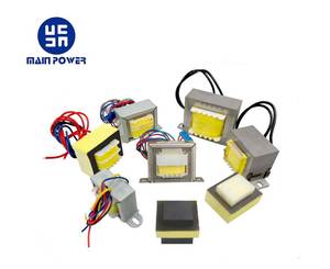
Square 60Hz 220V Auto Distribution & Voltage Sensing Transformers
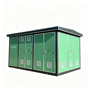
Modular Three-Phase Autotransformer High/Low Voltage Compact Transformer Substation (YBW Model) IP44
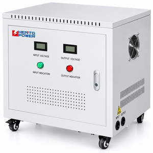
Factory Direct Sale 10KVA 220V to 380V 3 Phase Toroidal Aluminum Winding 50/60Hz Auto Transformers
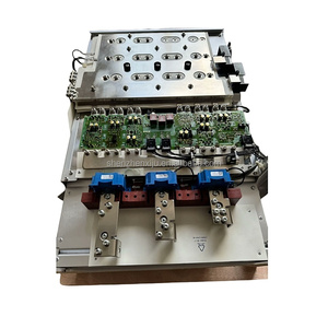
Replacement Fan & Voltage Potential Transformer 6SL3352-7AE32-1AA1 S120 MICROMASTER PX Series
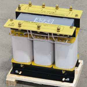
SBK 3-Phase Auto Transformer 415V 380V 220V 240V Isolation Voltage PT System 20KVA-150KVA Copper/Aluminum
15+
Years Engineering Expertise
500+
Global Industrial Clients
25 MVA
Max Capacity / 66kV Class
CE & BIS
ISO 9001:2015 Approved
1. The Technical Evolution of CE Certified Potential Transformers (Voltage Transformers)
Potential Transformers (PTs)—interchangeably categorized as Voltage Transformers (VTs)—form the critical metrological backbones of modern medium-voltage (MV) and high-voltage (HV) transmission lines, industrial switchgear, and commercial power distribution grids. Operating as specialized instrument transformers, their primary mandate is to step down exceptionally high system line voltages (ranging from 3.3kV up to 66kV and beyond) to standardized, safe, and ultra-precise secondary output values—typically 110V, 100V, or 110/√3 V—suitable for feeding delicate fiscal revenue meters, digital protection relays, phase-angle monitors, and SCADA telemetry units.
Achieving compliance under European CE marking mandates (specifically the Low Voltage Directive 2014/35/EU and the Electromagnetic Compatibility Directive 2014/30/EU) requires far more than basic step-down capability. A CE Certified Potential Transformer manufacturer must guarantee strict electromagnetic isolation, absolute thermal stability under sudden network surges, minimal phase angle displacement, and zero interference from ambient electromagnetic fields. In high-stakes power installations, even a micro-variance in voltage transformation accuracy can compound into massive fiscal losses during utility billing or trigger catastrophic protection blind spots during grid fault transients.
Information Gain: Inductive vs. Capacitive Potential Transformers (IVTs vs. CVTs)
Modern electrical engineering delineates potential transformers into two primary operational architectures: Inductive Voltage Transformers (IVTs) and Capacitive Voltage Transformers (CVTs). Inductive PTs utilize electromagnetic coupling via wound high-permeability silicon steel or nanocrystalline cores, making them the absolute gold standard for indoor switchgear and MV outdoor networks up to 66kV due to unrivaled accuracy (up to Class 0.1). Conversely, CVTs integrate capacitive voltage dividers with electromagnetic tuning reactors, dominating ultra-high voltage (UHV) transmission above 115kV where physical insulation costs scale non-linearly.
Cast Resin Insulation (Epoxy)
Ideal for indoor medium-voltage switchgear. Vacuum cast epoxy resin provides extreme mechanical strength, fire-retardant safety, zero oil leakage risk, and partial discharge resilience (< 5pC at 1.2Un).
Oil-Immersed Hermetic Units
Engineered for harsh outdoor substations. Employs refined mineral or synthetic ester oils with expansion bellows to prevent atmospheric ingress, ensuring long-term dielectric breakdown resistance.
SF6 / Gas-Insulated Switchgear (GIS) PTs
Ultra-compact, maintenance-free designs integrated within SF6 gas enclosures. Perfect for space-constrained urban substations requiring full immunity against atmospheric pollution and oxidation.
2. Engineering Parameters: Accuracy Classes, Thermal Burden & Ferroresonance Safeguards
Selecting the optimal CE certified potential transformer requires rigorous technical evaluation of metrological precision, rated thermal burden (VA rating), and transient grid stability mechanisms. Miscalculating these operational parameters can compromise protective relaying during asymmetrical phase-to-ground faults or cause thermal runaway in instrument windings.
Metrological Accuracy Classes & Application Vectors
Potential transformers are manufactured across distinct metering and protection accuracy classes governed by international standards IEC 61869-3, IEEE C57.13, and IS 3156:
- Class 0.1 & 0.2 / 0.2S (Revenue & Tariff Metering): Designed for power exchange boundary points, Independent Power Producer (IPP) tie-in substations, and industrial power plants. Guarantees ratio error within ±0.1% to ±0.2% across 80% to 120% of rated primary voltage.
- Class 0.5 & 1.0 (Industrial Monitoring & Control): Standard operational tier for factory sub-metering, panel instrumentation, SCADA inputs, and energy management systems (EMS).
- Class 3P & 6P (Relay Protection & Fault Detection): Specialized protective windings engineered to maintain accuracy under severe fault conditions (ranging from 5% of rated voltage up to the rated voltage factor limit, e.g., 1.9 Un for 8 hours). Ensures directional overcurrent and distance relays actuate instantly during phase faults.
Technical Matrix: Comparative Specifications Across Insulation Architectures
| Insulation Type | Voltage Range (kV) | Accuracy Classes | Partial Discharge Level | Primary Application Environment |
|---|---|---|---|---|
| Vacuum Cast Resin (Dry-Type) | 0.6kV – 36kV | 0.1, 0.2, 0.5, 3P, 6P | < 5 pC @ 1.2 Un | Indoor MV Switchgear, Data Centers, Mining |
| Oil-Immersed Hermetically Sealed | 11kV – 66kV | 0.2s, 0.5, 3P | < 10 pC @ 1.2 Un | Outdoor Grid Substations, Solar/Wind Farms |
| Gas-Insulated (SF6 / Eco-Gas) | 33kV – 132kV+ | 0.2, 0.5, 3P | < 2 pC @ 1.2 Un | Indoor GIS Substations, Urban Power Hubs |
| Toroidal & Auto-PT Units | 110V – 3.3kV | 0.5, 1.0 | N/A (Low Voltage) | Industrial Fan Motors, Railway Drives, VFDs |
Mitigating Ferroresonance in Ungrounded & Weak Networks
Ferroresonance is a non-linear resonant phenomenon that occurs between the non-linear magnetizing inductance of a potential transformer and the capacitive reactance of transmission lines or cable networks. Triggered by switching operations, blown fuses, or single-phase grounding faults, ferroresonance can cause severe overvoltages (2.0 to 3.0 p.u.) and intense core saturation, resulting in extreme overheating, insulation breakdown, and transformer destruction.
To eliminate ferroresonance risks, our CE certified potential transformers incorporate specialized engineering countermeasures:
- Open-Delta Residual Voltage Windings (Damping Resistors): Installing an external damping resistor across the open-delta auxiliary secondary winding dissipates trapped harmonic energy without affecting normal balanced operating conditions.
- Low Flux Density Core Designs: Operating the core magnetic induction well below saturation thresholds (typically at 0.8 to 1.2 Tesla) ensures the transformer retains inductive linearity even during temporary system overvoltages.
- Integrated Ferroresonance Suppressors: Microprocessor-controlled electronic damping circuits that dynamically apply damping resistance only when resonance frequency spectra (16.6Hz, 25Hz, or 50/60Hz sub-harmonics) are detected.
3. Enterprise Strengths, Brand Authority & Manufacturing Capability
Volta Transformers—a premier brand owned by Volta Green Energy Pvt. Ltd. and backed by the prestigious Pooja Group of Industries (Established in 2001)—stands as a global leader in high-reliability electrical transformation and measurement equipment. Headquartered in the industrial heartland of Vadodara, Gujarat (India), our state-of-the-art manufacturing campus spans over tens of thousands of square feet equipped with precision automated winding bays, vacuum pressure impregnation (VPI) plants, and ISO/IEC 17025 accredited high-voltage testing laboratories.
ISO 9001:2015 & BIS Certified
Fully compliant with international quality management systems and Bureau of Indian Standards (BIS IS 1180: Part 1: 2014 & IS 3156), guaranteeing stringent process repeatability.
High-Capacity Production Bay
Capable of engineering custom power transformers up to 25 MVA / 66 KV class, alongside thousands of cast resin and oil-immersed potential transformers annually for OEM global markets.
Full In-House Routine & Type Testing
Every unit undergoes strict Partial Discharge screening, Lightning Impulse Withstand testing (BIL up to 325kV), induced overvoltage testing, and dielectric oil Dissolved Gas Analysis (DGA).
With a satisfied global clientele exceeding 500+ utilities, EPC contractors, railway operators, and heavy industrials across Europe, the Middle East, Southeast Asia, and the Americas, Volta Transformers brings an unyielding commitment to engineering precision, zero-defect quality, and full lifetime technical support.
4. Future Procurement Trends & Technological Roadmaps for Potential Transformers
The global electrical equipment landscape is undergoing a monumental paradigm shift driven by grid decarbonization, massive integration of variable renewable energy (VRE), and the digitalization of power substations. B2B procurement managers and electrical systems architects must align their equipment specifications with the following critical technology trends transforming potential transformers over the next decade:
1. Transition to Digital Substations (IEC 61850-9-2 Process Bus)
Conventional potential transformers rely on heavy copper secondary wiring to transmit analogue 110V signals across vast substation yards to control rooms—introducing voltage drops, burden constraints, and severe safety hazards if secondary circuits are shorted. Future-ready substations are rapidly migrating toward digital instrument transformers (NCITs) and optical potential transformers. These units digitize voltage waveforms directly at the primary sensor and transmit real-time sampled values (SV) via Ethernet fiber-optic networks using the IEC 61850-9-2 process bus protocol, eliminating copper loss and enhancing personnel safety.
2. Rise of Low-Power Passive Voltage Transformers (LPVTs)
In smart medium-voltage secondary distribution networks, compact Low-Power Voltage Transformers (LPVTs)—utilizing resistive or capacitive voltage dividers—are rapidly displacing traditional iron-core PTs. LPVTs provide linear voltage output signals (e.g., 3.25V / √3) directly compatible with modern digital IEDs and smart micro-grid controllers. Key advantages include ultra-compact dimensions, zero saturation, immunity to ferroresonance, and massive weight reduction in modular compact substations (YBW models).
3. Eco-Friendly Biodegradable Insulation Media
Environmental regulations and corporate ESG mandates are accelerating the phase-out of traditional mineral oils in outdoor potential transformers. Next-generation PTs utilize natural and synthetic ester fluids derived from renewable plant bases. Ester fluids boast high fire points (>300°C), self-extinguishing safety characteristics, and 100% biodegradability within 28 days, rendering them mandatory for installation in environmentally sensitive watersheds, offshore wind platforms, and dense urban centers.
4. AI-Driven IoT Condition Monitoring & Asset Health Analytics
Modern CE certified potential transformers are increasingly integrated with online asset health monitoring suites. Micro-sensors embedded within the resin cast or oil tank continuously track real-time partial discharge activity, winding thermal hot-spots, dielectric oil moisture content, and vibration spectra. Advanced predictive maintenance algorithms process this telemetry to detect insulation degradation months before catastrophic failure occurs, shifting maintenance from reactive schedules to data-driven reliability-centered strategies.
5. Frequently Asked Questions (FAQ) for B2B Buyers & Electrical Engineers
Below are expert answers to critical technical questions frequently raised by procurement officers, panel builders, and substation project managers when sourcing CE certified potential transformers:
What does CE Certification mean for a Potential Transformer?
CE Certification verifies that the potential transformer complies with all mandatory European Union health, safety, and environmental protection directives. Specifically, it guarantees conformity with the Low Voltage Directive (LVD 2014/35/EU) and Electromagnetic Compatibility Directive (EMC 2014/30/EU), enabling unrestricted entry into EU markets and assuring global buyers of uncompromised operational safety.
How do I select the correct rated burden (VA) for a PT?
The rated burden (expressed in Volt-Amperes or VA) represents the maximum secondary electrical load (connected meters, relays, wiring resistance) the PT can supply while maintaining its specified accuracy class. Calculate the total VA requirement of all series-connected instruments plus cable losses, then choose a standard PT burden rating (e.g., 15VA, 30VA, 50VA, 100VA) that operates between 25% and 100% of its rated capacity for optimal accuracy.
What is the difference between a Potential Transformer and a Power Transformer?
A Potential Transformer is an instrument transformer designed to provide extremely accurate voltage measurement signals at very low power levels (typically under a few hundred VA), operating under near open-circuit secondary conditions. A Power Transformer is built to transfer bulk kilowatts or megawatts of electrical energy between voltage levels at high power efficiency under continuous heavy load.
Why is Partial Discharge (PD) testing crucial for cast resin PTs?
Partial Discharge refers to localized electrical breakdowns within tiny voids or micro-cracks inside the solid epoxy insulation. Left undetected, PD gradually erodes resin dielectric strength, culminating in catastrophic catastrophic insulation failure. Our CE certified PTs undergo 100% PD screening to guarantee levels below 5 Pico-Coulombs (< 5pC) at 1.2 times rated voltage.
What is Voltage Factor (Vf) and why does it matter during phase faults?
The Voltage Factor specifies the temporary overvoltage multiplier a PT can withstand without core saturation or winding damage during grid disturbances. For example, a Voltage Factor of 1.9 Un for 8 hours ensures the transformer can operate continuously during an ungrounded single-phase-to-earth fault, allowing maintenance crews time to isolate the grid anomaly.
Can Volta Potential Transformers be customized for multi-ratio outputs?
Yes. We specialize in custom OEM engineering. Our potential transformers can be configured with multiple secondary taps or separate secondary cores (e.g., Core 1 for Class 0.2 metering, Core 2 for Class 3P relay protection, and Core 3 for open-delta residual voltage supervision) within a single compact housing.