Electricity networks are carrying heavier and less predictable loads. The International Energy Agency’s Electricity 2024 report expects global electricity demand to grow by about 4% annually through 2026. More substations will therefore need dependable transformer capacity. In this environment, Hermetically Sealed Transformers offer a practical response to moisture, oxygen, and maintenance risks.
Their sealed tank contains the insulating oil without a conservator or continuous contact with outside air. This detail matters in humid coastal substations, dusty industrial yards, and remote renewable-energy sites. Reduced oxygen exposure can slow oil oxidation and limit sludge formation. The design also reduces the chance of moisture entering through a breathing system. Fewer external fittings can mean fewer inspection points. That is useful, but not magical.
The U.S. Department of Energy’s 2024 distribution-transformer efficiency rule highlights the long-term energy cost of transformer losses. Its analysis projects substantial national energy savings across the equipment’s service life. CIGRE publications also emphasize condition monitoring, oil quality, thermal performance, and loading discipline. These points support a broader engineering view: reliability depends on both design and operation. A hermetically sealed tank cannot correct overloads, poor installation, or inadequate protection settings.
No transformer design fits every project. Sealed units may complicate pressure management and internal fault assessment. Engineers must check fault levels, ambient temperature, oil type, expansion behavior, and service access before selection. The strongest case appears where low maintenance, compact installation, and environmental exposure matter most. Choosing wisely requires evidence, not fashion. That is why the question is worth examining carefully.
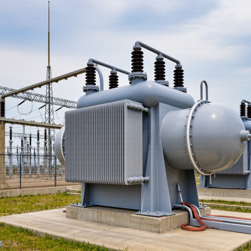
How Hermetically Sealed Transformers Are Designed
Why Choose Hermetically Sealed Transformers?
Hermetically sealed transformers are designed around one practical goal: keeping insulating oil away from air and moisture. Engineers place the active core and windings inside a welded, oil-filled tank. A flexible corrugated wall absorbs oil expansion as temperature changes. No conservator tank is needed. Fewer external openings also reduce possible leakage points.
The manufacturing process demands discipline. The tank is vacuum-dried before filling. Filtered oil enters under controlled vacuum, limiting trapped air and water. Technicians then inspect welds, gaskets, bushings, and pressure-relief devices. IEC 60076-1 and IEC 60076-3 guide routine, dielectric, and temperature-rise testing. Small defects matter. A weak seal can become a serious failure after years of heating and cooling.
Energy performance also influences the design. The U.S. Department of Energy’s 2024 distribution-transformer rule estimates 3.6 quadrillion British thermal units in energy savings over 30 years. Lower no-load and load losses therefore require careful magnetic steel selection, winding geometry, and conductor sizing. In field service, technicians still check oil temperature, load patterns, and visible tank deformation. Sealed construction reduces maintenance, but it does not eliminate inspection. No design is perfect. Some installations may need improved monitoring, especially where overloads, salt air, or sharp temperature swings are common.
Why Choose Hermetically Sealed Transformers? - How Hermetically Sealed Transformers Are Designed
| Design Dimension | How It Is Designed | Typical Technical Data | Why It Matters | Design Considerations |
|---|---|---|---|---|
| Sealed Tank Construction | The transformer tank is continuously welded and sealed after the active part and insulating liquid are installed. The enclosure is designed to prevent direct contact between the liquid and ambient air. | Leak-tight steel enclosure; welded or gasketed access covers; pressure-tested before service | Reduces moisture ingress, oxidation, and contamination of the insulating liquid. | Weld quality, flange design, gasket compatibility, and pressure testing are essential for long-term reliability. |
| Insulating Liquid Protection | The liquid is filled under controlled conditions, commonly after vacuum treatment of the tank and active part. The sealed system limits exposure to oxygen and humidity. | Typical mineral insulating liquid moisture target: commonly below 20 mg/kg at commissioning, subject to applicable standards and project requirements | Helps preserve dielectric strength and slows liquid aging. | Liquid quality must be verified through sampling, dielectric breakdown, moisture, acidity, and dissipation-factor tests. |
| Pressure and Vacuum Capability | The tank, cover, radiators, and fittings are engineered to tolerate thermal expansion, transport loads, and specified pressure or vacuum conditions without permanent deformation. | Common factory checks include leak testing and pressure or vacuum testing; exact limits depend on tank design and applicable standards | Prevents air entry during cooling and reduces the risk of leaks or structural damage. | The design must account for oil expansion, altitude, ambient temperature, and emergency operating conditions. |
| Thermal Expansion Management | Instead of using a free-breathing conservator, the sealed tank accommodates liquid expansion through controlled tank flexibility, a gas cushion, or an engineered expansion chamber. | Typical liquid temperature-rise limits are commonly 55 K or 65 K, depending on insulation system and standard | Maintains a closed system while allowing the liquid volume to change as temperature varies. | The expansion method must be coordinated with tank strength, liquid fill level, and pressure-relief settings. |
| Cooling System | Heat is transferred from the windings and core to the insulating liquid, then through tank walls, radiators, or corrugated panels to the surrounding air. | Common cooling classifications include ONAN; larger units may use ONAF with fan-assisted airflow | Provides reliable heat dissipation without requiring the tank to be opened to the atmosphere. | Radiator area, airflow, solar loading, installation altitude, and ambient temperature affect the rated capacity. |
| Core Design | The magnetic core is built from insulated, grain-oriented electrical steel laminations arranged to reduce eddy-current and hysteresis losses. | Typical power-frequency core loss is designed within the project specification; no-load loss depends on core material, flux density, and frequency | Improves energy efficiency and limits no-load heating throughout the service life. | Flux density must be controlled to avoid excessive excitation current, noise, and localized heating. |
| Winding and Insulation System | Conductors are insulated with materials selected for electrical stress, thermal class, mechanical strength, and compatibility with the insulating liquid. | Copper or aluminum conductors; insulation design coordinated with rated voltage, impulse level, and temperature rise | Withstands operating voltage, short-circuit forces, switching events, and thermal cycling. | Axial and radial clamping, conductor transposition, cooling ducts, and impulse distribution require coordinated design. |
| Moisture and Contamination Control | The sealed enclosure, sealed cable boxes, and protected bushings are selected to minimize entry paths for water, dust, and corrosive atmospheric contaminants. | Suitable for humid, dusty, coastal, and industrial environments when the enclosure and accessories are correctly specified | Reduces insulation deterioration and maintenance caused by environmental exposure. | External surfaces still require inspection for corrosion, coating damage, and blocked cooling passages. |
| Pressure-Relief Protection | A pressure-relief device is installed to release abnormal internal pressure caused by an internal fault or rapid gas generation. | Pressure-relief settings are selected according to tank strength and transformer design; alarm and trip contacts may be provided | Limits the possibility of tank rupture and supports safer fault management. | Relief-device discharge direction, access for inspection, and coordination with protection systems must be considered. |
| Monitoring and Accessories | Temperature indicators, liquid-level indicators, pressure or vacuum gauges, and electrical protection contacts are selected according to the transformer rating and installation requirements. | Typical monitoring includes winding or liquid temperature, liquid level, internal pressure, and pressure-relief status | Allows operators to identify overheating, leakage, abnormal pressure, or loading problems early. | Instrument accuracy, alarm thresholds, wiring protection, and remote monitoring interfaces should be specified before manufacture. |
| Factory Testing | The completed transformer is subjected to routine electrical, mechanical, liquid-quality, and leak tests before shipment. | Typical tests include winding resistance, turns ratio, insulation resistance, no-load loss, load loss, applied-voltage, induced-voltage, and leak testing | Confirms that manufacturing quality and performance meet the specified design requirements. | Additional type or special tests may be required for short-circuit withstand, temperature rise, impulse performance, or seismic qualification. |
| Maintenance Profile | The closed design removes the routine need for breather servicing and conservator inspection associated with free-breathing transformer designs. | Maintenance commonly focuses on visual inspection, liquid sampling, temperature and pressure checks, bushing inspection, and connection tightening | Can reduce routine maintenance activities and help maintain consistent liquid quality. | A sealed design does not eliminate maintenance; periodic condition assessment remains necessary for safe operation. |
FAQS
Its main purpose is keeping insulating oil away from air and moisture. This reduces oxidation and helps preserve dielectric strength. The design is practical, not magical.
A flexible corrugated tank wall absorbs oil expansion during temperature changes. No conservator tank is required. The tank must remain flexible and sound.
The tank is vacuum-dried before filling. Filtered oil enters under controlled vacuum. This limits trapped air and water inside the tank.
Technicians inspect welds, gaskets, bushings, cable boxes, and pressure devices. They also check cooling surfaces and tank condition. Small defects can become serious later.
No, it mainly changes the maintenance approach. Inspectors still check oil stains, rust trails, paint bubbles, and unusual pressure readings. Sealed does not mean maintenance-free.
An infrared scan can show abnormal hot zones on the tank or connections. The transformer should have a stable load during scanning. Trained interpretation remains necessary.
Selection should begin with the duty, not the catalogue. Confirm power, voltage ratio, frequency, insulation level, and fault withstand. Also check altitude, temperature range, enclosure protection, clearances, and lifting points.
Keep commissioning records, inspection photographs, and trend data together. Record ambient temperature and load beside each reading. A simple baseline often reveals trouble earlier.
Conclusion
Hermetically Sealed Transformers are designed with a completely enclosed tank that isolates the transformer oil and insulation system from outside air and moisture. As the oil expands or contracts with temperature changes, the sealed structure manages internal pressure without relying on a traditional conservator. This helps reduce oxidation, moisture absorption, and insulation aging, supporting stable electrical performance and extending service life. The protected tank also limits contamination and lowers the risk of oil deterioration caused by repeated contact with the atmosphere.
Compared with conventional conservator transformers, this design can offer a simpler structure, reduced maintenance requirements, and improved resistance to environmental conditions. However, performance still depends on load level, ambient temperature, altitude, cooling conditions, and installation quality. Regular inspection should include checking for leaks, unusual pressure, temperature changes, corrosion, and signs of insulation or oil degradation. When selecting a unit, users should consider rated capacity, operating environment, protection requirements, maintenance access, and compatibility with the electrical system.