Transformer Technical Blog & Knowledge
Explore in-depth technical guides, power grid insights, and industrial transformer innovations.
Industry Updates & Electrical Solutions
Stay informed on power, distribution, dry-type, and renewable duty transformer technology.
Expertise Driven Electrical Engineering
Professional insights from Gujarat's premier power transformer manufacturing leaders.
What Are the Top Pad Mounted Transformers?
Choosing the top Pad-Mounted Transformers is not a simple brand comparison. Utility engineers examine capacity, voltage class, enclosure strength, safety features, and service history. A transformer that performs well in a dry suburban vault may struggle beside a coastal road.
Thomas A. Prevost, a recognized transformer specialist, emphasizes, “Transformer reliability depends on disciplined design, installation, and maintenance.” That principle shapes this guide. The strongest units usually combine efficient cores, sealed oil systems, corrosion-resistant cabinets, and clear internal layouts. Dead-front construction can reduce exposure during routine switching. Loop-feed designs may also support better network flexibility.
Small details matter.
A properly sized transformer should handle present demand without wasting energy at light load. It should also leave practical room for future growth. Engineers often compare sound levels, temperature rise, fault protection, and cable-access space before selecting a model. A locked cabinet, reliable grounding point, and visible warning labels can prevent avoidable maintenance problems.
Still, no universal winner exists. Site conditions change the answer. Soil moisture, salt air, flooding risk, vandalism exposure, and local utility standards can overturn a convenient ranking. Even a premium transformer can fail when ventilation, loading, or installation practices are poorly managed.
This article evaluates leading Pad-Mounted Transformers through performance, safety, durability, serviceability, and lifecycle value. It considers both manufacturer specifications and field realities, including cramped equipment pads, muddy work areas, and overheated summer enclosures. Some judgments remain imperfect because long-term field data is not always publicly available. That limitation deserves attention, not concealment.
What Is a Pad-Mounted Transformer?
What Are the Top Pad Mounted Transformers?
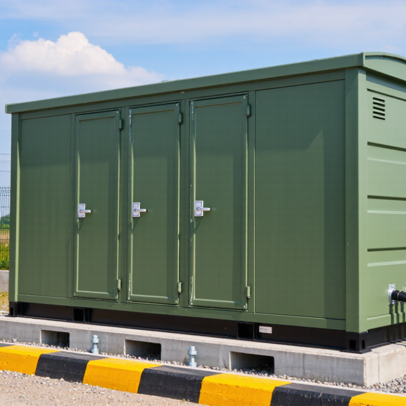
A pad-mounted transformer is a ground-level, tamper-resistant unit installed on a concrete pad. It converts medium-voltage electricity into safer low-voltage power for homes, businesses, and light industrial sites. Underground cables enter through sealed compartments, keeping the equipment compact and protected from weather. Most units use liquid insulation, although dry-type designs suit selected indoor or environmentally sensitive locations.
The most practical configurations are radial-feed and loop-feed transformers. Radial units are simpler and often cost less. Loop-feed models can maintain service when one cable section needs isolation. Dead-front construction reduces exposed energized parts during maintenance.
However, enclosure design, grounding, fault ratings, and ventilation matter more than appearance. IEEE C57.12.34 provides widely used requirements for pad-mounted equipment, including enclosure and construction considerations.
Efficiency deserves equal attention. The U.S. Department of Energy’s 2024 distribution-transformer rule projects about 1.3 quadrillion British thermal units in energy savings over 30 years. That figure covers distribution transformers broadly, not pad-mounted units alone, but it shows why core losses deserve careful review.
A transformer running beside a parking lot may hum quietly while losing energy continuously.
Field selection should match load growth, ambient temperature, short-circuit duty, and maintenance access. A neat catalog rating is not enough. I have seen planning decisions overlook future electric-vehicle charging demand. That mistake can make a correctly sized transformer feel undersized within a few years.
How Pad-Mounted Transformers Work
What Are the Top Pad Mounted Transformers?
How Pad-Mounted Transformers Work
A pad-mounted transformer lowers medium-voltage electricity for nearby homes, offices, and small industrial sites. It sits inside a locked steel enclosure on a concrete pad. Underground cables enter through the base. Inside, a magnetic core transfers energy between primary and secondary windings without a direct electrical connection. The voltage changes, while the frequency stays constant. Simple in principle. Demanding in practice.
When power reaches the primary winding, alternating current creates a changing magnetic field in the core. That field induces a lower voltage in the secondary winding. Load-break switches, fuses, and surge arresters help control faults and lightning-related overvoltage. Mineral oil or an approved alternative removes heat from the windings. During field inspections, technicians check oil condition, bushing seals, grounding, and enclosure corrosion. A quiet hum is normal, but rising noise can signal stress.
The best unit depends on load growth, fault levels, climate, and maintenance access. The U.S. Energy Information Administration reports that transmission and distribution losses commonly remain near 5% of delivered electricity. Efficient transformer design can reduce a portion of those losses, especially under continuous loading. U.S. Department of Energy analyses have identified distribution transformers as consuming roughly 2.5% of national electricity use. That figure deserves attention. Yet efficiency ratings alone do not choose the right transformer. Oversizing may waste energy at light loads, while undersizing can accelerate insulation aging. Real sites are less tidy than spreadsheets. Room for uncertainty should remain in the design.
What Are the Top Pad Mounted Transformers? - How Pad-Mounted Transformers Work
| Transformer Type | Typical Rating Range | Phase Configuration | Primary Voltage | Secondary Voltage | How It Works | Best-Fit Applications | Key Advantages | Important Considerations |
|---|---|---|---|---|---|---|---|---|
| Single-Phase Radial-Feed | 10–167 kVA | Single-phase | Typically 2.4–19.9 kV | Typically 120/240 V | Receives medium-voltage power through one incoming feeder, reduces the voltage by electromagnetic induction, and supplies a low-voltage service to the connected load. | Individual homes, small commercial buildings, rural services, and light-duty facilities. | Compact design, straightforward protection, lower installation cost, and suitable capacity for many small loads. | Power interruption can occur if the single feeder or transformer fails; capacity is limited for large three-phase equipment. |
| Single-Phase Loop-Feed | 25–167 kVA | Single-phase | Typically 2.4–19.9 kV | Typically 120/240 V | Uses two medium-voltage cable connections so the transformer can be connected to a looped distribution system, allowing the feeder to be sectionalized or rerouted. | Residential subdivisions, urban neighborhoods, and locations where service continuity is important. | Improved feeder flexibility, easier network sectionalizing, and better outage-management capability than radial-feed units. | Requires additional switching equipment, careful phase coordination, and more space for cable terminations. |
| Three-Phase Radial-Feed | 75–2,500 kVA | Three-phase | Typically 4.16–34.5 kV | Typically 208Y/120 V, 480Y/277 V, or 600 V | Uses a three-phase magnetic core and windings to step medium-voltage distribution power down to balanced three-phase utilization voltage. | Commercial buildings, schools, apartment complexes, manufacturing sites, and agricultural facilities. | Efficient delivery of three-phase power, good motor performance, and a broad range of available capacities. | A feeder fault may interrupt the entire transformer supply; grounding, phase balance, and fault-current calculations are essential. |
| Three-Phase Loop-Feed | 75–2,500 kVA | Three-phase | Typically 4.16–34.5 kV | Typically 208Y/120 V, 480Y/277 V, or 600 V | Connects to a looped medium-voltage feeder through multiple cable compartments or switching points, supporting isolation and restoration of sections of the circuit. | Data centers, hospitals, campuses, shopping centers, and other facilities requiring higher distribution flexibility. | Better service continuity, easier maintenance isolation, and improved operational flexibility. | Higher equipment and installation costs; switching procedures must follow the utility and site safety requirements. |
| Dead-Front Pad-Mounted Transformer | Typically 25–2,500 kVA | Single- or three-phase | Commonly up to 35 kV class | Selected to match the local utilization system | Medium-voltage connections are made with insulated separable connectors located behind a locked enclosure, with no exposed energized primary parts during normal access. | Public areas, residential developments, commercial sites, and installations with frequent personnel access. | Enhanced operator safety, reduced exposure to energized parts, and compatibility with modern underground distribution systems. | Requires compatible elbows, bushings, parking stands, and properly rated switching and grounding equipment. |
| Live-Front Pad-Mounted Transformer | Typically 25–2,500 kVA | Single- or three-phase | Commonly up to 35 kV class | Selected to match the local utilization system | Primary terminals are accessible within the enclosure and may include exposed energized parts when the transformer is energized, so access is restricted and work practices are more demanding. | Older distribution systems, restricted utility installations, and projects where existing equipment must be matched. | Can support established system designs and may have simpler legacy arrangements. | Greater arc-flash and contact risk; modern projects commonly prefer dead-front construction where applicable. |
| Mineral-Oil-Immersed Pad-Mounted Transformer | Approximately 25–2,500 kVA | Single- or three-phase | Commonly up to 35 kV class | Commonly 120/240 V to 600 V class systems | The core and coils are immersed in insulating liquid that provides electrical insulation and transfers heat to the tank and surrounding air. | General utility distribution, residential services, commercial distribution, and industrial sites where approved environmental controls are available. | Proven cooling performance, high efficiency, compact construction, and broad utility-service availability. | Requires spill containment and environmental review where applicable; fluid condition and tank integrity should be inspected. |
| Ester-Fluid Pad-Mounted Transformer | Commonly 75–2,500 kVA | Single- or three-phase | Commonly up to 35 kV class | Selected to match the facility distribution voltage | Uses a biodegradable natural or synthetic ester fluid for insulation and heat transfer instead of conventional mineral oil. | Indoor-adjacent outdoor installations, environmentally sensitive locations, renewable-energy sites, and facilities seeking improved fire performance. | Higher fire point than mineral oil, reduced environmental impact for many fluid types, and good moisture tolerance. | Fluid cost, temperature limits, compatibility, and local code acceptance should be confirmed during specification. |
| Renewable-Energy Interconnection Transformer | Typically 500–3,000 kVA | Three-phase | Inverter output to medium-voltage collection voltage | Often 480 V or another inverter-specific voltage | Steps inverter-generated power up to the collection or utility interconnection voltage and provides isolation, grounding, and impedance suited to the project. | Solar farms, battery-energy-storage systems, wind facilities, and distributed-generation projects. | Designed for bidirectional power flow, project-specific impedance, and integration with medium-voltage collection systems. | Harmonics, inrush current, grounding method, thermal duty, and utility interconnection requirements must be evaluated. |
Note: Rating and voltage ranges are representative industry values rather than universal limits. Final selection should be based on load calculations, fault-current levels, insulation coordination, cooling requirements, environmental conditions, applicable electrical codes, and utility specifications.
Key Types of Pad-Mounted Transformers
What Are the Top Pad Mounted Transformers?
Key Types of Pad-Mounted Transformers
Pad-mounted transformers support underground distribution systems in neighborhoods, commercial sites, and renewable-energy projects. Their sealed cabinets sit on concrete pads, reducing exposed wiring and improving public safety. The main choice is not simply capacity. It is the operating environment, load profile, and maintenance strategy.
Liquid-filled transformers remain common for outdoor distribution because insulating fluid removes heat efficiently. Single-phase models usually serve homes and small loads. Three-phase units suit apartments, factories, and commercial buildings. Radial-feed designs use one incoming supply path and offer simpler protection. Loop-feed transformers connect two supply paths, improving service flexibility during planned switching. Network transformers provide multiple-source operation, but their protection and coordination requirements are more demanding. Dry-type pad-mounted transformers avoid liquid insulation and may fit sensitive locations, although they can require stronger ventilation and more space. Field experience shows that “safer” does not always mean “easier.”
The U.S. Department of Energy estimates distribution transformer losses at roughly 60 billion kilowatt-hours annually. That figure makes efficiency important, even when no customer sees the transformer working. The IEA’s Electricity 2024 report projects global electricity demand growth near 3.2% annually through 2026. Higher demand may favor three-phase and loop-feed configurations, but oversized equipment can increase no-load losses.
Tips: Check future load growth before selecting kVA. Confirm fault-duty ratings, fluid containment, enclosure clearance, and local standards. Review seasonal loading, too. A transformer that looks adequate on paper may struggle during a hot afternoon peak.
Top Features That Define High-Quality Models
High-quality pad-mounted transformers begin with dependable insulation and enclosure design. IEEE Std C57.12.34 specifies requirements for dead-front pad-mounted units, including grounding, cabinet construction, and safe access. A strong enclosure resists rain, salt, insects, and accidental impact. Stainless or corrosion-resistant hardware helps, especially near coastal roads. The doors should close firmly, without forcing the hinges.
Efficiency matters beyond the nameplate. The U.S. Department of Energy’s 2024 Transformer Technical Support Document estimates that distribution transformers use about 2.5% of total U.S. electricity. Lower no-load losses can reduce waste throughout thousands of operating hours. High-quality models therefore use efficient cores, suitable conductor sizing, and verified temperature-rise performance. Small losses become expensive at scale. Still, efficiency claims need independent test records, not attractive brochures.
Field experience also points to practical details. A clear wiring diagram, accessible test points, and visible fluid-level indicators can shorten maintenance visits. Sealed tanks reduce moisture entry, while pressure-relief devices support safer fault management. IEEE testing guidance helps verify dielectric strength, winding resistance, and impulse performance before service. Load growth deserves attention too. A transformer selected only for today’s demand may run hot later. That mistake is common. Designers should review measured peak loads, harmonics, ambient temperature, and future electric-vehicle demand. Even then, no model is perfect; local soil conditions and installation quality can undermine excellent factory specifications.
What Are the Top Pad-Mounted Transformers? - Top Features That Define High-Quality Models
Common pad-mounted transformer ratings range from small residential units to large commercial and utility installations. High-quality models typically combine the correct kVA capacity with sealed weather-resistant enclosures, effective thermal performance, suitable insulation levels, low losses, safe compartmentalized construction, and reliable overload protection.
The chart shows commonly used standard transformer ratings in kilovolt-amperes (kVA). Actual selection should be based on calculated peak load, future capacity requirements, primary and secondary voltage, impedance, installation conditions, efficiency, and applicable electrical safety standards.
How to Choose the Right Pad-Mounted Transformer
What Are the Top Pad Mounted Transformers?
The top pad-mounted transformer is not always the largest or most efficient model. Choosing correctly starts with the site, not the catalog. Confirm the system voltage, phase arrangement, frequency, and required kVA. Then examine present demand and likely growth. Motors, welders, pumps, and battery chargers can create short peaks. A transformer sized only for average load may run hot. That mistake is common.
For outdoor distribution, compare liquid-filled designs by cooling method, insulation fluid, efficiency, impedance, and tap range. Mineral oil may suit familiar utility practices, while biodegradable ester fluid can offer advantages in sensitive locations. Check the enclosure rating, corrosion protection, lockable access, and clear working space. A concrete pad must support the weight and allow drainage. Flood-prone sites need extra attention. Small details matter.
Ask for verified test records, temperature-rise data, and applicable electrical certifications. Review the transformer’s noise level near homes, offices, or hospitals. Confirm short-circuit withstand ratings with the protection system. An experienced electrical engineer should check coordination, grounding, cable termination, and future capacity. Field inspections often reveal mismatched lugs or restricted ventilation after installation. I would not trust a clean calculation alone. Real loads change, and project assumptions can age badly. Keep maintenance access practical, even when space is limited.
FAQS
It is a ground-level unit installed on a concrete pad. It converts medium-voltage electricity into safer low-voltage power. Underground cables enter through sealed compartments. The enclosure protects equipment from weather and accidental contact.
They serve homes, offices, parking areas, shops, and light industrial sites. You may see one beside a driveway or landscaped boundary. Clear access around the enclosure remains important.
Radial-feed units are simpler and often less expensive. Loop-feed units can maintain service when one cable section needs isolation. The better choice depends on service continuity requirements and system design.
Look for strong doors, sealed openings, corrosion-resistant hardware, and secure locking. The enclosure should resist rain, salt, insects, and accidental impact. Doors should close smoothly without forcing the hinges.
Confirm voltage, phase arrangement, frequency, and required capacity. Review measured peak loads, not only average demand. Motors, pumps, welders, and battery chargers can create short peaks. Future charging equipment may increase demand quickly.
A transformer can lose energy continuously, even when it hums quietly beside a parking lot. Efficient cores and suitable conductors reduce long-term waste. Small losses become costly across many operating hours.
Choose dead-front construction, reliable grounding, pressure-relief protection, and suitable fault ratings. Request test records for insulation, winding resistance, and temperature rise. Visible fluid indicators and accessible test points can shorten service visits.
Check soil stability, drainage, flood risk, ambient temperature, and available working space. The concrete pad must support the equipment securely. Restricted ventilation or mismatched cable connections can cause trouble later. Clean calculations are not enough.
Liquid-filled designs often suit outdoor distribution applications. Dry-type designs may fit selected indoor or environmentally sensitive locations. Compare cooling, insulation, fluid type, ventilation, and maintenance needs. No option is perfect.
Request verified efficiency data, temperature-rise results, fault withstand ratings, wiring diagrams, and certification records. Review noise information for nearby homes, offices, or care facilities. Attractive brochures alone should not decide the purchase.
Conclusion
Pad-Mounted Transformers are ground-level electrical devices designed to safely reduce medium-voltage electricity to a lower voltage for homes, businesses, industrial facilities, and public infrastructure. Installed inside secure, weather-resistant enclosures, they connect underground distribution systems to local power networks while minimizing visual impact and improving safety. Their operation relies on electromagnetic induction, transferring electrical energy between windings and adjusting voltage levels to meet the needs of connected equipment.
The main types include single-phase and three-phase models, with options suited to different loads, locations, and distribution requirements. High-quality Pad-Mounted Transformers are defined by efficient performance, strong insulation, corrosion-resistant construction, reliable cooling, effective protection, and easy maintenance access. Choosing the right unit requires evaluating voltage ratings, capacity, load characteristics, installation conditions, environmental exposure, safety requirements, and future expansion plans. A carefully selected transformer can support stable power delivery, reduce energy losses, and provide dependable long-term service.

Blog Tags: