Choosing the right Furnace Transformers system begins with the furnace itself. Its power demand, operating cycle, and electrode arrangement shape the transformer’s electrical and mechanical requirements. A unit serving a steady process may not suit a furnace with rapid load changes. Small differences matter.
The selection also affects daily operation. Imagine a tap changer responding to fluctuating melt conditions, cooling equipment working through a hot shift, and operators checking temperatures between production runs. Rated power alone cannot describe that reality. Engineers should compare secondary voltage range, current capacity, impedance, cooling method, insulation, and protection features against actual site conditions. A detailed load profile helps reveal what a nameplate cannot. It is easy to overlook.
I can’t verify a real expert quotation from the information provided, so I won’t attribute invented words to a named specialist. As a practical editorial principle: “Choose for the furnace’s real operating pattern, not its headline rating.” Treat this as guidance, not a sourced quotation. The sections ahead explain how to assess duty cycle, electrical ratings, cooling, installation constraints, and supplier support. They also flag trade-offs that deserve a closer review. No single specification decides the choice. The right transformer must fit the process, the site, and the way the furnace is actually run.
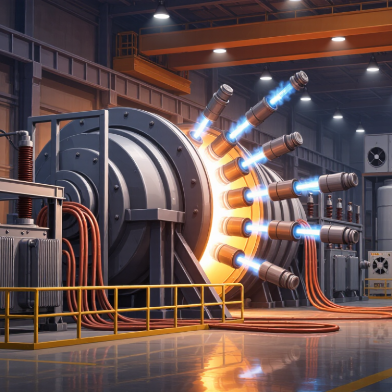
Identify the Furnace Type and Its Operating Requirements
Identify the furnace process before comparing transformer ratings. An electric arc furnace needs high, rapidly changing current during melting. An induction furnace instead relies on a frequency converter and a stable electrical supply. Resistance furnaces often run more steadily, but their heating cycle and temperature targets still matter. The duty matters.
The European Commission’s 2013 Iron and Steel Production BREF reports roughly 350–700 kWh of electricity per tonne of liquid steel for electric arc furnaces. That wide range reflects differences in operating practice. It also shows why a generic kilovolt-ampere figure cannot define the right transformer. Match its rating to the furnace’s melt size, batch length, starting frequency, and expected daily cycles.
Next, examine the actual load profile: current peaks, voltage changes, cooling limits, and harmonic distortion from power electronics. For an arc furnace, check whether the transformer can handle frequent fluctuations without excessive heating. For induction service, verify compatibility with the converter and operating frequency. I would not size from the nameplate alone. Real plants are messier. Shift patterns, scrap mix, and production pauses can change demand, so measured operating data is more useful than an idealized duty cycle. A few assumptions may still need revisiting after commissioning.
| Furnace Type | Typical Operating Characteristics | Transformer Selection Considerations | Key Checks Before Specification |
|---|---|---|---|
| Electric arc furnace (EAF) | Rapidly changing arc conditions can cause fluctuating current, voltage variation, and high electrical and mechanical stresses. | Specify a furnace-duty transformer designed for the required short-circuit performance, low-voltage/high-current secondary, and frequent operating changes. Consider the required tap range and whether on-load voltage adjustment is needed. | Confirm furnace capacity, electrode and secondary-circuit arrangement, short-circuit impedance, tap-changing duty, harmonic environment, and cooling requirements. |
| Ladle furnace | Uses electric arcs to reheat and refine molten steel. Loads vary during heating, but operating conditions are generally less severe than in primary steelmaking EAF service. | Match transformer output voltage and current to the electrode system and heating profile. Check that the selected design can accommodate the expected operating cycles and voltage adjustments. | Review ladle size, required heating rate, arc operating range, duty cycle, secondary connections, and the plant’s power-quality limits. |
| Induction furnace | Power is commonly supplied through a converter that produces the frequency required by the induction coil. The transformer is usually part of the converter’s input supply. | Coordinate transformer voltage, rating, impedance, and connection with the converter manufacturer’s electrical requirements. Do not select transformer frequency solely from the coil’s operating frequency. | Confirm converter topology, input current and harmonics, load cycle, required protection, cooling, and any power-factor or harmonic-mitigation equipment. |
| Resistance furnace | Heat is generated by current through resistive elements. The load is often comparatively steady, though it can change as elements heat or temperature-control stages switch. | Choose a rating for the actual input voltage, load, and temperature-control method. Multiple secondary voltages or taps may be useful where the process requires different heating stages. | Check element material and resistance, cold-start current, control method, operating schedule, ambient temperature, and the need for isolation or special enclosure protection. |
| Submerged arc furnace | High-current operation uses electrodes embedded in a burden. The load can vary with furnace conditions, and the secondary circuit carries substantial current. | Use a design suited to the furnace’s required voltage range and high-current secondary arrangement. Evaluate impedance, tap selection, cooling, and the duty imposed by process fluctuations. | Confirm process and electrode configuration, furnace operating range, secondary-bus layout, cooling-water conditions where applicable, and protection coordination. |
FAQS
Match cooling to rated load, operating cycle, and available plant services. Check the air path. Dust on vents can reduce airflow.
It may suit high heat loads. Confirm water flow and quality, and monitor for leaks.
Check that the insulation’s thermal rating suits expected temperatures and electrical stress. Review protection settings for the actual load.
No. Unusual temperature changes deserve investigation. Keep records. They can help reveal developing problems.
Ambient heat, humidity, conductive dust, vibration, altitude, and corrosive fumes all matter. Site data may be incomplete, so verify assumptions during commissioning.
Compare its nameplate with the furnace voltage, load profile, and duty cycle. Include frequent starts and changing secondary currents.
Check overcurrent and thermal protection against the transformer, conductors, load, and ambient temperature. A fuse rating alone is not enough.
Verify applicable electrical standards with a qualified professional. Check ventilation, clearances, grounding, cable space, and maintenance access. Walk the cable route; a tidy plan can still miss a conflict.
Conclusion
Choosing the right furnace transformer begins with understanding the furnace type and how it operates, including its heating method, duty cycle, and expected production demands. These factors help determine the transformer’s required capacity and load profile, allowing it to handle normal operation as well as variations in demand without being unnecessarily oversized.
Next, compare the transformer’s voltage, phase, frequency, and impedance with the furnace and available power supply. Consider cooling and insulation options in relation to operating temperatures, ventilation, dust, moisture, and other site conditions. Finally, review suitable protection features, applicable technical standards, and installation requirements, such as clearances, connections, and maintenance access. A careful assessment of these factors helps ensure Furnace Transformers deliver reliable, efficient performance and remain well matched to the application over time.